THE PROCESS:
After forgetting to make a group over the break, my partner Nic and I got put in the 'left-over' group on arriving back to class.
Our Group:
- Nic | architecture - third year
- Sinead | architecture - third year
- Aimee | architecture - third year
- Andrew | landscape - fourth year
- Charbel | construction - fourth year
- Matt | construction - fourth year
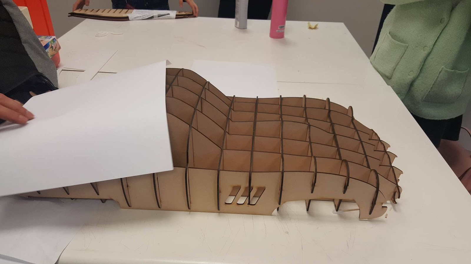
However unorganized we may have been in the mid-semester break we made up for in class. We got straight down to business and sliced the Ferrari online model using the program Slicer for Fusion360.
We decided to make 7 x 15 slices as we thought this was sufficient in order to get the level of detail in the model that we desired.
The software generated these slices for us but they needed some cleaning up on AutoCAD before we could laser cut them as we did not want random lines and cut outs on our model.
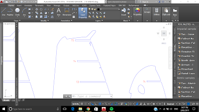 |
| before cleaning up file |
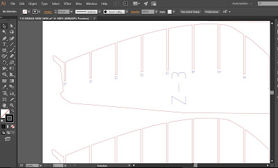 |
after cleaning up file and changing RGB colours
|
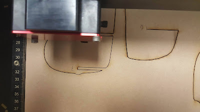
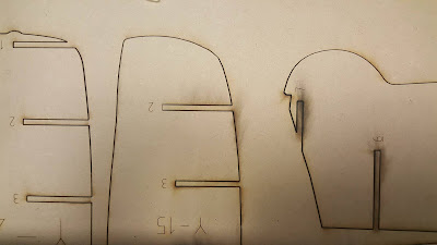
The laser machine burnt the edges of some of our pieces, but this doesn't matter as they will be covered with the aluminium skin. All the pieces cut through perfectly due to us correcting the illustrator file, except for one piece (Y-6) where the edge details ran into a slot, and the details were cut off the piece. This won't matter too much as they are only very small pieces and we can super glue them onto the assembled model.
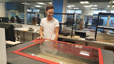 |
| Nic and I hogging both Laser cutters |
 |
| our slices coming to life |
 |
| burnt edges using laser cutter |
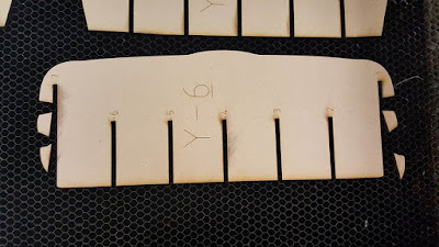 |
| details on this piece were cut off the slice |
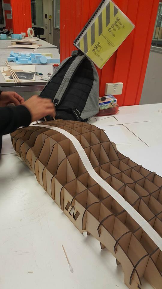
Luckily we were able to use mistakes of groups that were ahead of us to help smooth out our group's process. We added a 0.5mm tolerance to the slots which made constructing our Ferrari
very easy and quick - and because of the large tolerance we didn't break any of the pieces when inserting them. We went from the group who formed last, to the second group who had a constructed Ferrari model - solid work!
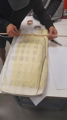
We then saw another group wrap their model in masking tape which revealed the contours of the model more effectively. We decided this was a good idea and did the same.
 |
| Matt taking taping to another level |
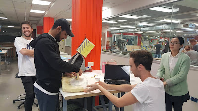 |
| It takes 6 people to tape up a car... |
After taping we were left with a weird, beige and white patchwork car that can't move. Despite what our little car looks like, I started to see why people paid the big bucks for these luxury cars and their sleek profiles, sexy curves and long lines. However, these sexy curves became slightly less appealing when I realised I'd be shaping the aluminium to fit them.
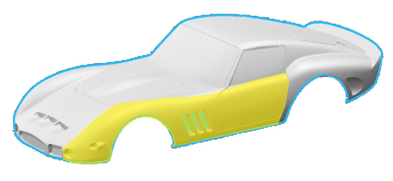
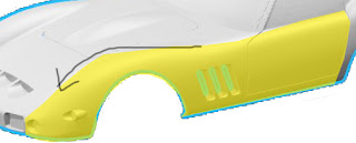
It was time to divide the car up into parts for us to individually work on. Our group decided to focus on our strengths and tried to pick sections that were similar to what we did best in the first assignment - either the bowl, the Taurus, the blister or the tray. Fresh from my Tasmanian adventures over the mid-sem break, I was feeling inspired and I was feeling ambitious. Pity these feelings soon faltered. I thought I could try tackle the front fender, and maybe even the second one while I was at it!
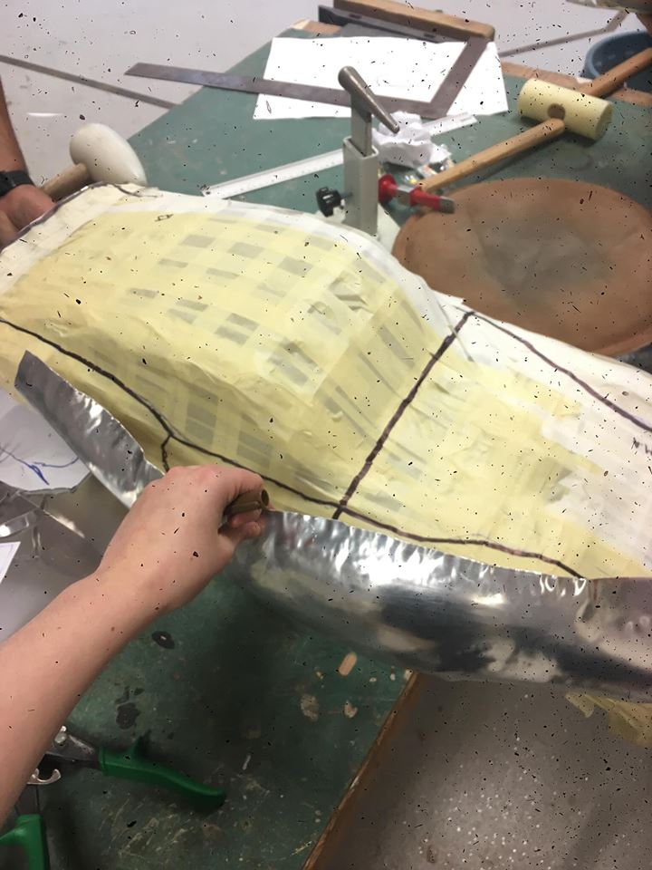
The yellow below shows the section I will make:
First thing to do was to make a pattern of my piece on a sheet of paper.
Paper proved a useful tool as it clearly showed areas that needed to be stretched and areas that need to be shrunk by putting the flat piece over the curves of the model.
Once I had my template I traced it onto a sheet of aluminium adding a little extra just to be on the safe side so to not run out of material. Then I cut the metal using tin-snips and then filed down the sharp edges using a metal file.
If only I had stopped at this point for the day... instead I was eager to power on and get a good start on my piece. Except I was so eager that I didn't really spend enough time planning out how I would go about creating the shape. I turned into another 'Bam Bam' and unleashed my inner crazy.
 |
| Marking out the area I wanted to stretch to achieve a curve |
I used the templates we used to create the reverse curve and the larger radius end of a nylon mallet. I was trying to achieve the curve over the wheel as shown below by stretching the metal over the curve. But this was a very bad decision and really set me backwards. In hindsight I should have used the malleability of the annealed aluminium and bent the shape as much as I could first.
Instead I continued with the warped piece I had created, not entirely sure what I should next do to salvage my efforts. I tried to flatten out the creases and shrink the edges of the curve to tighten the radius. I did this using the mallet and sandbag in the same way as when creating the bowl. I then put the shape into the English wheel to try and straighten out the shape so it curved less dramatically by using the flat wheel option. I also decided to cut down on excess metal as it was getting in the way. The results are pictured below (blame the strange specked effect of the photos on Nic's phone, which I had to use as I forgot to bring my own in).
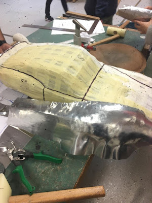
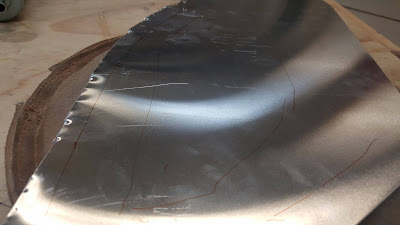
The English Wheel worked well to straighten out the rear door side of the piece. As you can see below, the car model is actually flat and does not curve outwards like my metal piece did. I put it back under the English Wheel again with the flat wheel to push against the curve I had created at the start. This helped a little but was still not as flat as the car should be.
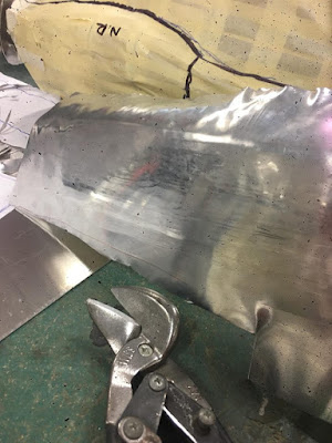
I then tried to tighten the curve of the piece that sits above the wheel. I did this by using a medium sized curved T-Dolly and a nylon mallet (to reduce the marks left on the metal). I placed the area I wanted to curve and hit outwards to try and emulate the ridge line of the curve.
This was quite successful as you can see below but the shape still need tweaking. As the bottom of the door was sticking out and the curve of the wheel was a little too high.
I didn't leave myself with enough material at the start and had space that I needed to fill on the wheel curve as shown by the black line. Because my curve was already too high, I tried to flatten it a little and stretch the material over to meet the black line.
When I pushed on the piece it seemed to line up quite well, so I knew that I had enough material to create a good fit.
Before I worked on tweaking the top curve of the wheel I thought it as time to create the front curve where the fender meets the bumper (near the headlight). I did this by using the wooden reverse bowl template and the small radius of a nylon mallet to create folds so to shrink in the edges, like when making the bowl. I then smoothed out the creases using the larger radius end of the mallet.
Dan came round to check on how I was doing and saw me struggling along, getting less enthused by the minute by being frustrated in a room with 30+ people banging metal. He got me to snap out of my mood and to stand back and look at the piece I had created. What was working? What sections were obviously wrong? How can I change this?
These simple questions helped me regain some control on the situation and I started to see the project with much needed fresh eyes. For starters, from my 'Bam Bam' state early in the project, I had stretched and curved the length of the piece, when it should have been straight. The English Wheel had rectified part of this to a point, but the warped piece was in some serious need of shrinking.
Dan suggested with only having one more week till submission that I should use the shrinker machine as it was quick and effective. I as slightly hesitant as it creates ridges and marks in the surface that are ugly and hard to reverse. But I really needed to do something quick, so he brought me over to the shrinker and showed me how to use it.
Firstly I shrunk the front bumper end of the piece to create a rounded end.
I then needed to gently flatten out the curve I had created where the door meets the window. I still needed this curve but it needed a smaller radius than what I had previously given it. I used a curved T-Dolly and a flat ended mallet.
Next I focused on shrinking the edge of my wheel curve as it was too high and needed to be brought closer down to the bonnet.
I then used the Shrinker once again to shrink the bottom half of the door panel as mine had stuck out due to excessive stretching. This created a lot of marks, but my shape quickly transformed into one with a much better fit.
Me, gently using the Shrinker to flatten out the curve I had wrongly put into the length of my piece.
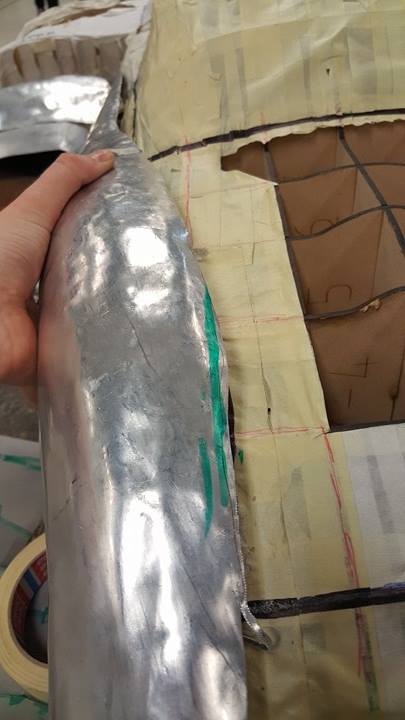
In the picture below I had evaluated the progress I had made using the Shrinker so far. I came up with two areas to work on:
- the area marked in green on the left needed to be stretched so to meet the black line of my template on the model. I did this by using a rounded mallet and a sandbag and hit diagonally, trying to stretch it towards the bonnet.
- the area marked in green on the right needed to be shrunk even more, to create a tighter fit to the model. I did this by using the Shrinker
The shrinking and stretching worked well but the curve above the wheel was still too high. I decided to use the mallet to reduce the height of the curve by flattening it out gently. I used 3 different shaped ends and found the rounded end of the flat mallet to be the most effective as the size was similar to the radius I was trying to create.
This technique worked but the curve was still too high so I started hitting the piece with a mallet directly onto the model. This created big dents but it did bring the curve down to the size I wanted it to be.
To remove the dents I had created I used a medium sized curved T-Dolly and tapped out the large marks. This however was changing the shape of the curve, which was not what I wanted.
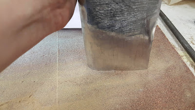
It was time for me to create a tool to smooth my surface more effectively. I found some timber in the bin and rounded off the edges on one end using the sanding wheel.
Next I cut the piece in half to make it easier to use. I used the other half as a sanding block for hand sanding.
Finally, I hand sanded the curved edges to create a smoother surface that wouldn't mark the surface of my metal.
I used the curved edge of my timber tool to smooth out the dents and bumps I had made by tapping lightly on the flat end with a mallet.
This was successful, but the light tapping did stretch the metal a little, enlarging the radius of the wheel curve once again. I used the large mushroom T-Dolly to bring back the shape so it hit the black line once again.
Next step was to fix the front curve near the headlights. The spherical T-Dolly and the round end of a tapered T-Dolly were the perfect size and shape to use to produce nice curves.
The edge was much higher than the model so I marked out an area to do some shrinking on the Shrinker.
I then smoothed out the ridges and marks with the spherical T-Dolly and sharpened the curve with a tapered T-Dolly.
To help reduce the severity of the marks the Shrinker made, I put the flat door part of my piece under the English wheel but light enough to not alter the shape. This was somewhat successful, but the marks were still very obvious.
 |
| sanding the edges |
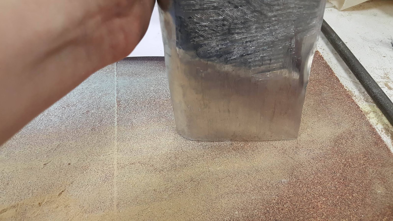
I decided I needed to sand down my piece electrically to produce a nicer surface finish. 40 & 60 grit sandpaper cylindrical drill attachments helped sand this quickly and hit the small and difficult curves.
This was the finish after 20 minutes of sanding. I thought it would turn out more evenly but that was probably a result of me using such a small device to sand a large area. The shrinker marks were reduced a lot and a more uniform finish was achieved than before sanding.
I found random high grit sandpaper in the FAB LAB which i used with my pre-made sanding block to hand sand the entire piece. By sanding it from a low grit to a high grit, I managed to achieve a more smooth appearance.
The final step (hurrah!) was to polish my piece. I applied Brasso onto some rag, evenly rubbed it over the entire surface and buffed it until shiny. It absolutely stunk of toxicity, next time I will definitely try my natural oil & vinegar approach.
I'm happy with the progress I made in the last 10 days on my piece. My metal piece went from a warped, alien shape to something that soundly resembles a Ferrari's front fender. My mood progressed from enthusiastic at the start, to 'Bam Bam' mode, to frustrated, to content.
I'm very happy with the shape in the end, I have to thank Dan a lot on that one - had he not helped me get my head back into the game I definitely would not be presenting something I was proud of today.
I would have liked the finish to be more smoothed and polished looking, however I am happy with the effort I put into making it look better than it did after the Shrinker marks were left all over it. Ideally I would not have used the Shrinker, but it helped sort out my shape very well.
This assignment has taught me a lot about how to accurately shape metal and how NOT to (I did a lot of the latter). I found it was more useful than the first assignment in this regard, as it pushes you out of auto-pilot mode and really makes you consider every step you take.
THE FINISHED PRODUCT:
I was skeptical as our group met up to piece together our little Ferrari. We hadn't spent a lot of time working together on our pieces due to differing schedules and different progress stages. I was worried that we'd have a jumble of incoherent metal pieces, but was pleasantly surprised when our Ferrari looked pretty good. It wasn't amazing but the overall shape and joints met up quite well for 6 people working on parts individually.
Unfortunately one of Andrew's pieces (the windscreen) went M.I.A in the workshop, so we were missing that which was a pity.
I think that our group worked quite well, we all got along and worked efficiently together. However, we could have improved our communication skills and tried to work at the same time together to work off each other's pieces more effectively.